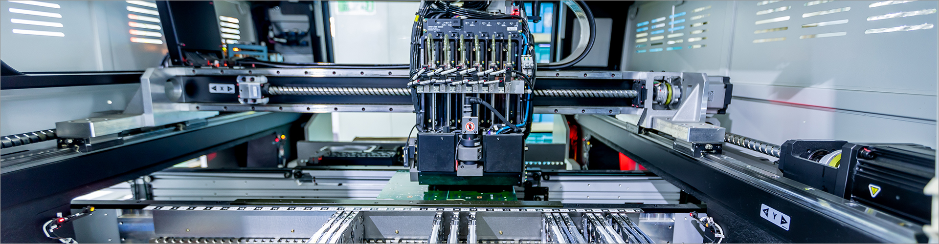

Consistent sheet metal assembly depends on three linked controls: accurate fit-up, repeatable fixturing, and inspection at the right checkpoints. I recommend starting with clean, deburred parts, locating each component from defined datums, and checking critical dimensions before permanent fastening or welding. A fixture should control position without forcing parts into alignment, while inspection should verify both part-to-part fit and the final assembly function. At Jinhui, I use this sequence to help manufacturing teams reduce rework risk and create clearer production instructions for sheet metal assemblies.
Click here to get more.
This guide explains how to prepare sheet metal components, select and use fixtures, inspect assembled parts, and communicate requirements to a manufacturing supplier. The recommended method applies to enclosures, guards, brackets, cabinets, frames, machine covers, and other fabricated assemblies. Exact tolerances and inspection frequency should always follow the approved drawing, applicable specifications, and the functional needs of the product.
Fit-up is the controlled positioning of sheet metal components before fastening, welding, riveting, or other permanent joining. Good fit-up begins before parts reach the assembly table. I first confirm the revision level, material, thickness, bend orientation, hole pattern, and required surface condition against the approved production documents.
Edges and holes should be free from loose burrs, chips, oil, and contamination that could prevent two surfaces from seating correctly. A burr can create a false gap, damage a coated surface, or shift a component away from its intended datum. Parts should also be identified by part number or batch information so that mixed revisions do not enter the same assembly.
For a practical pre-fit check, I verify that formed flanges are not cracked, bends are not visibly overworked, and protective films or coatings will not interfere with joining. If a coating must remain intact, the assembly method should account for clamp marks, heat exposure, and access for inspection. These checks are simple, but they prevent a fixture from compensating for a basic part-quality problem.
The drawing should identify the surfaces or features that control the assembly. A typical locating strategy uses a primary surface, a secondary surface, and a tertiary feature to constrain movement while avoiding unnecessary over-constraint. The familiar 3-2-1 locating concept can be useful, but the actual number and position of locators must match the part geometry.
I normally assemble from the most stable reference structure outward. For example, a base panel may establish the primary plane, side panels may locate against controlled bends or stops, and smaller brackets may be added after the main envelope is verified. This sequence reduces the chance that an early component hides a dimensional error in a later component.
A fixture provides repeatable location and controlled restraint during assembly. It may be a dedicated weld fixture, a modular fixture table, a checking fixture, a simple nest, or a combination of stops and clamps. The best choice depends on production volume, assembly complexity, required repeatability, product variation, and the cost of making or changing the tooling.
| Production situation | Practical fixture approach | Primary consideration |
|---|---|---|
| Prototype or low volume | Adjustable stops, modular plates, and hand clamps | Fast changeover and low tooling investment |
| Repeated medium-volume assembly | Dedicated nests with replaceable locators | Repeatability and maintenance access |
| High-volume or highly repeatable work | Dedicated fixture with controlled clamping and poka-yoke features | Cycle consistency and error prevention |
| Multiple related product versions | Modular or adjustable fixture system | Changeover time and configuration control |
Locators should contact stable, accessible areas and should not interfere with welding guns, rivet tools, screwdrivers, or inspection instruments. Clamps should hold the part against the locators rather than pull the part into a forced position. Excessive clamping force can deform thin sheet, close a designed gap, or create springback after release.
Sheet metal can move when heat, fastening force, or residual stress is introduced. To reduce movement, I recommend a joining sequence that balances the assembly instead of concentrating heat or force in one area. Tack locations, weld length, fastener order, and clamp release timing should be defined in the work instruction when they affect final geometry.
As a shop-floor example, a specified 0.5 mm fit-up gap should be treated as an engineering requirement only when the drawing or process specification calls for it; it should not be assumed to be suitable for every joint. When no gap is defined, the supplier and buyer should agree on the functional requirement, such as flushness, clearance, sealing, or weld access. This distinction prevents an informal rule from replacing a product-specific acceptance criterion.
Inspection is more effective when it is divided into incoming part checks, in-process fit-up checks, and final assembly verification. Waiting until the complete assembly is finished can make the source of an error difficult to identify. I prefer checkpoints that are close to the operation they control, especially before a joint becomes inaccessible.
jinhui are exported all over the world and different industries with quality first. Our belief is to provide our customers with more and better high value-added products. Let's create a better future together.
Inspection tools should match the tolerance and feature. Calipers may support general dimensional checks, while height gauges, gauges, templates, coordinate measuring equipment, or dedicated checking fixtures may be more appropriate for critical geometry. A measurement is useful only when the reference, method, instrument capability, and acceptance limit are clear.
For example, a 90-degree formed flange may be checked with an angle gauge or a suitable fixture, but the acceptable angular deviation must come from the product requirement. Similarly, a 2 mm hole-position error may be insignificant for one clearance hole and unacceptable for a precision mounting interface. I therefore separate “appearance acceptable” from “functionally acceptable” in inspection records.
Forcing a panel against a fixture may produce an acceptable appearance while storing stress in the assembly. After the clamp is released, the part can move, and the final hole pattern or mounting face may no longer match the intended position. If force is needed, I stop and investigate part variation, bend allowance, burrs, fixture condition, or an incorrect assembly sequence.
Too many fixed locators can create competing constraints, especially when formed parts have normal dimensional variation. The result may be difficult loading, inconsistent seating, or visible distortion. A better approach is to define the required degrees of control, use stable primary references, and allow noncritical features enough freedom to settle naturally.
A clean-looking assembly can still have misaligned holes, incorrect internal clearances, or a distorted mounting surface. Visual inspection remains valuable for scratches, weld appearance, sharp edges, and obvious defects, but it cannot replace dimensional and functional checks. Critical characteristics should be measured and recorded according to the control plan.
Repeatability improves when the design, process, fixture, and inspection plan use the same reference logic. I recommend marking critical datums on the drawing, identifying inspection points, and showing the fixture contact areas in the work instruction. Photographs or simple diagrams can help operators understand orientation, clamp order, and acceptable joint conditions.
Fixture maintenance should also be planned. Locating pins, stops, bushings, and clamp faces can wear, collect debris, or become damaged during handling. A basic maintenance check before production and after a tooling change can prevent gradual drift that would otherwise appear as unexplained assembly variation.
For low-volume work, modular fixtures can provide flexibility without committing to a fully dedicated tool. For stable, repeated production, dedicated tooling may reduce operator interpretation and shorten loading time, although the investment should be evaluated against volume, change frequency, and the cost of nonconforming assemblies. I help buyers compare these factors before recommending a fixture approach.
When requesting a quotation, provide the 3D model, 2D drawings, material and finish requirements, joining method, critical-to-function dimensions, expected annual or batch volume, and inspection documentation needs. If the design is still developing, identify which features are fixed and which may be optimized for manufacturability. This gives the supplier enough context to evaluate access, bend sequence, fixture requirements, and inspection method.
At Jinhui, I can support the discussion from fabrication through assembly planning, including fit-up review, fixture concepts, joining sequence, inspection checkpoints, and packaging considerations. I do not treat a generic tolerance or fixture design as suitable for every product; I align recommendations with the assembly’s geometry, material, volume, and functional interfaces. Where requirements are unclear, I recommend resolving them before production rather than relying on assumptions at the assembly station.
The practical answer is to control sheet metal assembly in this order: prepare and verify the parts, establish clear datums, select a fixture that locates without distortion, join using a defined sequence, and inspect critical features before and after permanent assembly. This method makes errors easier to detect and gives both the buyer and supplier a common basis for acceptance. It also supports more predictable quality when products move from prototype to repeat production.
As a next step, review one assembly drawing and mark its primary datums, critical interfaces, joining sequence, fixture contact points, and inspection checkpoints. Then ask your supplier to explain how the proposed process will control alignment, distortion, surface protection, and final function. If you are sourcing custom sheet metal assemblies, send Jinhui your drawings, material requirements, target volume, and inspection expectations for a practical manufacturing review and quotation.
Contact us to discuss your requirements of Sheet Metal Assembly Guide: Fit-Up, Fixtures, and Inspection. Our experienced sales team can help you identify the options that best suit your needs.
34
0
0
All Comments (0)
If you are interested in sending in a Guest Blogger Submission,welcome to write for us!


Comments